Using Tactile Pressure Mapping To Improve High Voltage Switches
Keywords: high voltage switches arching, improve high voltage switches, pressure mapping, tactile pressure evaluation, fuji prescale pressure map, h-bridge switch design
Summary: High voltage switches need perfectly aligned contact surfaces to prevent arching. Using the Fuji Prescale pressure mapping system engineers can detect and prevent failures of switches, and design better ones thanks to the ease of use of the Prescale films to map tactile pressure.
Source: Mark A. Kemp et.al., Redesign of the SNS Modulator H-Bridge for Utilization of
Press-Pack IGBTs, IEEE Transactions on Dielectrics and Electrical Insulation, September 2008
Written by Igor Mateski
The Role of Tactile Pressure Balance
High voltage power switches that operate in conditions of fast-switching devices that need significant amperage are susceptible to various loads and defects.
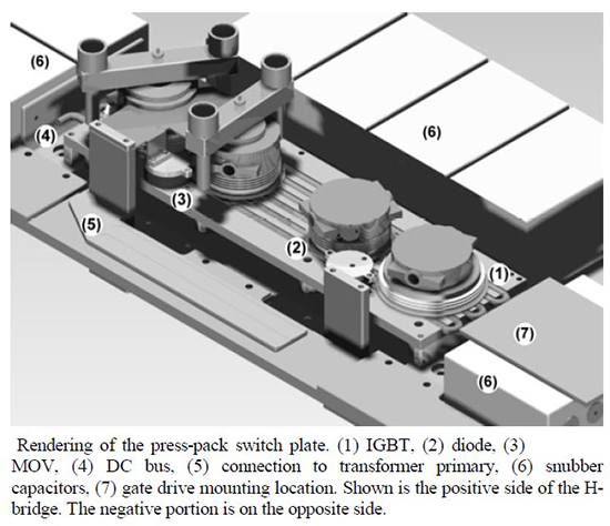
H-Bridge switchplates are a perfect example of high voltage switches that operate for hundreds of thousands of hours and manage power on ranges of 75-115kV and peaks of up to 11MW. Establishing fast and reliable contact and circuit-braking needs perfect alignment and nominal tactile pressure of the contacting surfaces every time.

In some cases, because of the voltage and power range, long operation life and huge count of switch cycles these H-Bridge switchplates sometimes break, and in several cases were even culprits for fires. Investigative research has shown that these defects are caused by arcing which in turn is an effect of poor tactile pressure profile between the contacting surface. This is why running regular maintenance checks with pressure mapping systems can prevent switch failures or even bigger accidents.
Defects of Tactile Pressure Balance Deviations
When the tactile pressure profile between two contacting surfaces has deviated from the factory settings, the high voltage that flows through the contact can cause arcing.
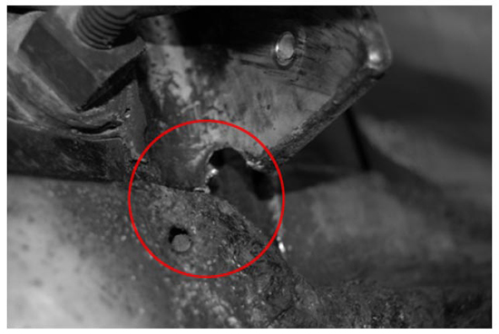
These arching events are responsible for very high temperatures that in turn cause mechanical damage to the contact surfaces and other surrounding elements of the H-bridge, as is shown on the image below:

In some cases arcing can result in welding of the contacting surfaces and in that case the mechanical joints of the H-bridge can break during a switch-off procedure, as is the case in the detail above. Such failures can be prevented if pressure mapping between contacting surfaces is a regular maintenance procedure.
Improving Designs With Fuji Prescale Pressure Mapping
Technicians should use the Fuji Prescale pressure mapping system in regular maintenance checkups. This will prevent major failures or fire accidents.
However, using the Fuji Prescale mapping system is not limited to the maintenance crew. Engineers also resort to the Fuji Prescale Film for development and improvement of H-bridge switches.
As the contacting surfaces are subject to strong pressure forces, engineers evaluate the thickness of the copper contact surfaces to see if the loads exerted by the springs are distributed evenly on the entire contacting surface. Thanks to the Fuji Prescale Film and the accompanying FPD-8010E digital measurement system engineers can precisely evaluate the pressure map and select the ideal copper plate thickness for the given nominal load force.
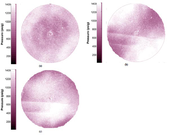
Below are developed Fuji Prescale films that show how thickness of the copper plates affects pressure distribution along the entire contacting surface.

Detail a above shows the pressure profile between the contacting surfaces. This surface is clamped from the center and a large-thickness force spreader is used so the pressure appears fairly symmetric.
Detail b shows a pressure map when force is not applied from the center, and pressure hotspots appear at the sides where the bottom clamping bar contacts the heat sink. This pressure concentrations will leave these areas poorly cooled.
Detail c shows a pressure map when a 2 inch in diameter, 2. 8 mm. thick shim was placed between the bottom clamping bar and the heat sink. This alteration resulted in a more even pressure distribution. This film also indicated areas of uneven surface on the bottom heat sink. These are shown as two horizontal bright lines on the left side of both Details b and c.
Thanks to the Fuji Prescale Film engineers can match the shim thickness and achieve proper tactile pressure. Any time a new change is introduced to the system a new pressure map readout should be made so that there is a feedback of how the new change affected the uniformity of the pressure map. The ideal scenario is presented in Detail a, where the spring loaders and shims establish a strong and uniform tactile pressure.
This way, engineers can design better switches, avoid arcing and enable proper cooling of the conductive contacting surfaces.
