Fuji Prescale Tactile Pressure Mapping For Improved Artificial Hips Design
Written by Igor Mateski
Keywords: stress magnitude, stress distribution, direct pressure mapping, tactile pressure mapping, pressure readout, hip replacement design, hip replacement materials
Summary: Total Hip Replacement requires minimal dimensions without sacrificing durability of the elements. Using Fuji Prescale Film, engineers discover the optimal dimensions and materials used for hip elements.
Pressure Forces in Artificial Hips
Artificial hips are one of the more complex prosthetics because the hip bone serves as a main pressure and force balancer in our body. The hip bone takes the spinal load and distributes this static force to the legs. Also, the dynamic loads that act on the hip bone in daily activities like walking, climbing stairs or sitting down further complicate matters when total hip replacement is required.
The spinal joint is considered static in comparison to the hip joints with the leg bones. Naturally, dynamic joints take more complex loads and are therefore susceptible to wear and tear. This study therefore, focuses on the hip joint with the leg bones, specifically, what combination of materials and dimensions of the Acetabular shell and liner is the ideal one for a durable hip replacement operation.
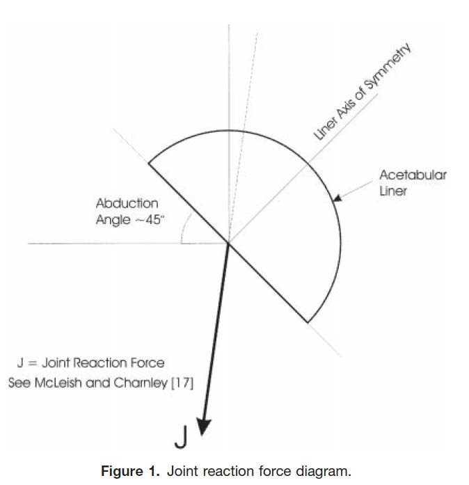
Below is a diagram of how load vectors are joined into a single reaction force that engineers use in measuring loads and tactile pressure on the Acetabular shell-Femoral head joint.

Using this diagram, engineers ran a battery of tests with a load force of F=3000N, which is the maximum load experienced by a 225lb human during gait. The tests were designed to establish which material and dimensions are optimal (generate minimal tactile pressure, and result with minimal ware and tare).
This research started to evaluate a hypothesis:
"Our hypothesis was that although the combination of the large head and the lower modulus of the highly crosslinked polyethylene would lead to lower stresses, the stresses would be excessive if the liner was extremely thin at 3 mm. Von Mises stresses at the articulating surface of the highly crosslinked liners were lower, when compared to conventional polyethylene, in every THR size examined. Specifically, however, the 38- and 46-mm inner diameter (ID) highly crosslinked polyethylene even at the extreme of only 3-mm thick had lower stresses than the 22-mm ID conventional liner of 5-mm thickness. These data indicate that the use of a large head against highly crosslinked material even at 3-mm thickness results in lower stresses than in an existing conventional 22-mm head and 5-mm thick combination."
How Engineers Map Tactile Pressure in Hip Joints
Every hip design starts with a FEA model. That way, engineers can quickly eliminate undesirable scenarios, and focus on few optimal choices of material and dimensions for the hip replacement.
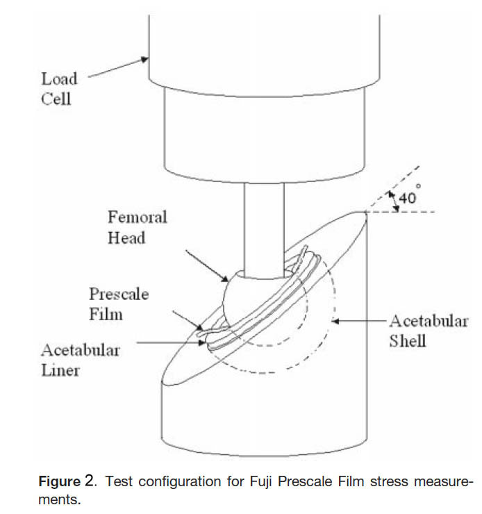
Below is a diagram of how engineers used a load rig to simulate the needed force of 3000N, and get good readouts of tactile pressure mapping.

As it is visible from the diagram, the artificial hip is reduced to the Acetabular shell, a matching liner, and the femoral head bearing. The Fuji Prescale Film is inserted between the Femoral Head and the Acetabular Liner and the pressure mapping is a direct readout of force distribution from the nominal 3000N load.
FEA vs. Actual Pressure Mapping Readouts
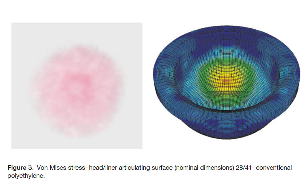
The FEA model and loading is identical to the actual lab rig for mapping tactile pressure between the Femoral Head and Acetabular Liner. The tactile pressure distribution was also measured at the Liner level because this element was tested both for dimension (5 vs 3mm thickness) and material (regular vs. highlycrosslinked polyethylene).

The FEA and rig testing models had several dimension sets and two different materials for the liner in order to verify the hypothesis, namely:
"In conventional polyethylene, all values (Von Mises stress, contact pressure, minimum principal stress, and shear stress) were higher in the 3-mm liners than in the 5-mm liners... In the subset of highly crosslinked polyethylene, all values were higher in the 3-mm liners than in the 5-mm liners. Among only 5-mm liners, stresses were lower in the highly crosslinked polyethylene in every case."
The benefit of the Fuji Prescale way of testing for optimal dimensions and materials is that with all the elements at hand, lab technicians and engineers can quickly get actual pressure readouts and accurate pressure maps. With developed Fuji Prescale pressure maps, even simple visual inspections can give accurate conclusions as to which elements/materials scenario is optimal for hip replacements.
