Bolted Joints Contact Pressure Mapping As Tool To Prolong Li-Ion Battery Charge
Written by Igor Mateski
Keywords: electrical contact resistance, tactile pressure measurement, pressure mapping, fuji prescale, battery manufacturing, electrical losses, bolted joints design, contact pressure measurement
Summary: Building efficient electrical vehicles requires efficient power supply. Li-Ion battery assemblies need strong wiring and bolted joint wiring is optimal. With proper bracket-bolted joints design electrical losses can be minimized. Using Fuji Prescale helps choosing the optimal bracket and bolted joints design for li-ion battery assemblies.
Why Contact Pressure Matters in Li-Ion Powered Devices
Car manufacturers are pressed to come up with environmentally friendly vehicles such as hybrid or pure-breed electric vehicles.
Nissan North America is one of the big industry players that started manufacturing electric vehicles and car batteries in Smyrna TN. While the greatest focus is on energy efficiency and mileage, the issue of power losses in vehicles is one of the issues that really make a difference.

Bolted joints tactile pressure affects power efficiency
Car battery assemblies experience up to 20% energy losses due to Electrical Contact Resistance (ECR). Electrical resistance manifests in heat, and in large battery assemblies these 20% are transformed into so much heat which cause serious concerns. As contact resistance depends on contact surface quality and tactile pressure, having a contact pressure map can help in reducing ECR. That way, the battery life will be prolonged, the risk of heat-induced battery deterioration will be minimized, and the risk of fire due to overheating will also be eliminated.
The Mechanics of Electric Contact Resistance in Bolted Joints Contacts
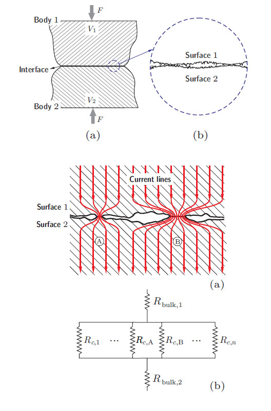
Manufacturing processes of any kind of metal components make it impossible to produce a completely flat surface. Even in the most sophisticated manufacturing processes the finished surface still has a degree of roughness. Below is a sketch of how this surface roughness affects electrical conductivity.

Surface roughness causes power losses ALT
Two contacting bodies in fact only establish electrical contact where the surface ridges of two bodies establish contact. These ridges account for about 2% of the entire body surface size. Each of these contacts has different height, and therefore each point of contact has a different tactile pressure. Since electrical conductivity depends on the tactile pressure, each conduction point is in fact a resistor which consumes electricity and dissipates heat that further increases the surface resistance.
In the car industry, this means that a large amount of electricity passes through a very small contacting surface, resulting in large electrical resistance which generates heat. In these high-power contacts, resistance-generated heat can grow so large that the two contacting surfaces melt, just like the spot-welding technique.
Mapping Tactile Pressure With Fuji Prescale To Visualize Resistance and Heat
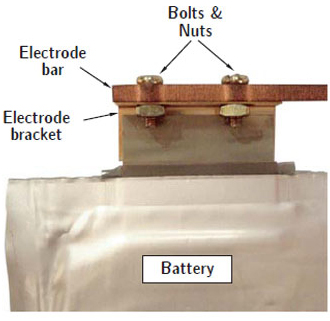
In high-power assemblies such as hybrid and electric vehicles, most battery contacts are established with bolted joints, as shown on Image 1. This means that relatively high tactile pressures can be easily achieved in order to maximize the actual conducting surface and consequently minimize power losses and prevent over-heating thanks to the materials' elastic characteristics.
But as surface roughness and machining processes create areas of uneven, out-of-flatness areas, the pressure distribution must be measured in order to precisely establish a proper tactile pressure every time. Inversely, measuring and visualizing these surface imperfections can create a map of the resistance and heat generating areas, as both resistance and heat are directly dependant on the tactile pressure.
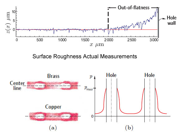
Below are actual screenshots of surface roughness measurements and a developed Fuji Prescale film revealing the out-of-flatness areas which in turn are the areas of highest resistance and highest heat:

Fuji Prescale Pressure Mapping on Bolted Electrode Brackets
In both measurements, the out-of-flatness areas account for increased tactile pressure. These areas are due to the punctuating of the mounting holes, usually done by stamping.
In this particular case two different materials were used (Copper and Brass), and as the Fuji Prescale film snapshots reveal, Copper turned out to be a better material for using brackets because of its better surface roughness profile after stamping.
Thanks to using the Fuji Prescale film to get actual tactile pressure mapping, engineers can design Li-Ion battery assemblies that will not be as prone to power loss.
By using proper machining techniques, bolt size and tightening force, ECR can be reduced from 20% down to only 7%. This also cuts down heat issues which prolongs battery life.
Related Case Studies for Lamination Pressure and Roller Defects :
Visualization and Measuring Tactile Pressure using Fuji Prescale and FDP 8010 Digital SystemUsing Fuji Prescale as Quality Assurance in Fuel Cell Manufacturing
Using Fuji Prescale As Comparative Measurement of Thermal Conductivity Between Aluminum Plates
